Search News
Industry Portal
Popular Tags
Servo troubleshooting when an axis oscillates at standstill
Author
Time
Click Count
When a servo axis oscillates at standstill, first establish whether the position command is steady and whether the load is physically moving. A buzzing motor, fluctuating feedback, and a visibly rocking carriage can point to different faults. Reducing gains immediately may quiet the axis while leaving a loose coupling, noisy encoder signal, or changing command unresolved.
Effective servo troubleshooting follows the evidence from command to feedback to mechanics. Capture the behavior before changing settings, correct identifiable faults, and adjust tuning only after confirming that the control loop is working with reliable feedback and a mechanically sound load.
Make the symptom safe to investigate
A stopped axis can still produce substantial torque. Keep personnel clear of the mechanism, retain protective functions, and use the machine’s approved service procedure. Before inspecting connectors, couplings, or brakes, isolate hazardous energy and secure any load that could fall or move. Safe torque off removes motor torque; it does not mechanically support a vertical axis.
Save the drive parameters and controller configuration before testing. Record the circumstances: whether oscillation begins immediately at servo enable, appears after a move, occurs only at particular positions, or changes as the machine warms up. Note recent work involving motors, encoders, transmissions, software, or tuning.
These conditions help narrow the search. A fault that starts after replacing a motor deserves a configuration check. A problem confined to one region of travel makes local binding or cable movement more relevant. Oscillation following a heavier fixture installation raises questions about inertia and structural flexibility.
Do not disconnect feedback or release a holding brake on an energized axis to isolate the problem. Any test involving reduced support, uncoupled components, or disabled control functions requires a mechanically safe setup and the applicable machine procedure.
Confirm what is actually oscillating
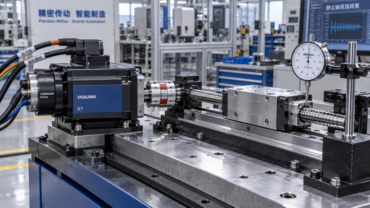
Watch the load as well as the motor. Use a safely positioned indicator or independent measurement where practical; do not rely entirely on the drive’s position display. A motor encoder measures motor movement, which may differ from load movement when a gearbox, belt, coupling, or screw introduces clearance or flexibility.
Capture synchronized traces of position command, actual position, following error, actual velocity, and torque-producing current or estimated torque. Include the drive enable state and brake command if available. In a dual-feedback system, record both motor and load feedback.
Choose a recording rate and duration that reveal the oscillation. A slow display can hide a fast vibration or make its frequency look misleading. Also check what each signal means: displayed velocity may be calculated from encoder position, and reported torque may be an estimate rather than a direct measurement.
These patterns guide the investigation; none proves a cause by itself. Noisy feedback can provoke real corrective motion, and mechanical resonance can produce a trace resembling excessive gain. Use an independent observation or a controlled test to separate them.
A stationary machine can still receive a changing command
“No motion command active” on an operator screen does not necessarily mean the drive receives a constant setpoint. Electronic gearing, synchronization, position offsets, probing functions, or compensation can modify the command beneath the displayed operating state.
Check the command at the drive interface, not just the program’s target position. If it changes, follow the signal back through the controller. Look for a master axis that is moving slightly, repeated correction updates, or a noisy reference. On systems using an analog speed or torque command, examine input noise and offset through the approved diagnostic method.
A documented local hold mode can help separate drive behavior from controller behavior, provided switching modes is safe and preserves the necessary load support. If the axis becomes stable with a fixed local reference, investigate the command path before modifying servo gains.
Check feedback integrity before tuning around the symptom
Review the alarm history even if no alarm is currently active. Intermittent feedback faults, communication errors, or supply disturbances may leave diagnostic records without producing a persistent trip. An absence of alarms does not establish that feedback is clean.
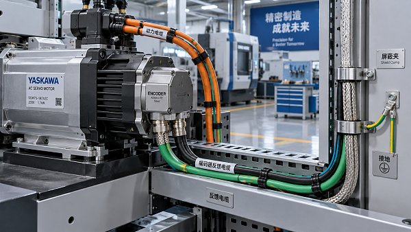
With power isolated, inspect encoder connectors for loose locking hardware, damaged contacts, contamination, and strain. Examine cable sections near moving carriers, tight bends, and recent repairs. A fault that appears at specific axis positions can be associated with cable flexing rather than a position-dependent mechanical defect.
Check shield termination, bonding, and separation from motor or other electrically noisy wiring against the equipment’s installation requirements. Shield arrangements vary between feedback interfaces; changing grounding connections by guesswork can introduce additional problems. Include the encoder supply and any intermediate connectors in the inspection.
After component replacement, confirm encoder type, resolution, polarity, motor identification, and any required commutation alignment. Incorrect settings can create unstable behavior even when the replacement component is healthy. Some errors appear during enable or initial movement rather than only at standstill.
Digital feedback can present intermittent errors or dropouts; analog sine/cosine feedback can suffer signal-quality problems. Use the drive’s available feedback diagnostics. A repeatable relationship with cable position or switching equipment is stronger evidence than a general suspicion of electrical noise.
Look for lost motion, friction, and flexible connections
A servo loop assumes that motor torque produces a reasonably predictable response. Loose components, backlash, and flexibility break that relationship. The controller may repeatedly correct an error while the load moves late, rebounds, or alternates between opposite sides of mechanical clearance.
Inspect couplings, pulley attachment, belt condition and tension, gearbox mounting, screw supports, and structural fasteners. Check accessible components according to the machine’s service procedure. A coupling can remain connected while losing stiffness or slipping under small reversing loads.
Distinguish backlash from elastic deflection. Backlash allows movement through clearance before the opposite contact face engages. Compliance stores energy as a belt, shaft, coupling, or structure twists or bends. Both can cause hunting, but they require different mechanical corrections and may respond differently to tuning.
Friction can create another pattern: the axis stays still while corrective torque builds, then breaks free and moves beyond the target. The cycle repeats as the controller reverses correction. This stick-slip behavior may involve guides, seals, screw assemblies, lubrication, or a brake that is not fully releasing. Increasing integral action can worsen it by building more correction during the sticking interval.
For vertical or counterbalanced axes, inspect brake operation and load-support behavior. Incorrect brake sequencing can make the motor work against a partly applied brake or allow movement during transfer of load support. Avoid changing holding torque or integral settings to compensate for a brake fault.
Do not assume that disconnecting the load provides a definitive tuning test. Removing it changes inertia and resonance, and a vertical mechanism may become unsafe. An unloaded motor test can help isolate a fault in an approved setup, but its stable behavior does not prove that the assembled machine is correctly tuned.
Use operating conditions to separate resonance from outside vibration
Compare the symptom at several safe positions and representative load conditions. Changes in frequency or severity can reveal the influence of extended structures, fixture mass, belt spans, or transmission stiffness. A long cantilever may behave differently when extended, even though the drive parameters remain unchanged.
Check whether adjacent machinery, pumps, fans, or shared frames introduce vibration. Where permitted, compare behavior with the suspected source stopped. If the disturbance remains while servo torque is safely removed and the load is securely supported, external excitation becomes more likely. However, disabling the servo also changes the mechanism’s stiffness, so this comparison needs careful interpretation.
Audible buzzing alone is weak evidence. Motor electromagnetic forces and switching behavior can produce sound without significant load movement. Judge the fault by measured displacement, current behavior, heating, and the machine’s positioning requirements rather than sound alone.
Adjust tuning only after the checks support it
Tuning becomes the appropriate next step when the command is steady, feedback is credible, and the mechanics are serviceable. Excessive loop bandwidth can excite a flexible mechanism, while unsuitable integral action can sustain slow hunting. Incorrect motor or load parameters can also undermine otherwise reasonable settings.
Follow the drive manufacturer’s tuning sequence because gain definitions and loop structures differ. Many drives use nested current, velocity, and position loops. Changing an outer loop cannot reliably compensate for an unstable inner loop, and changing several parameters together makes the result difficult to interpret.
Make one controlled change, capture another trace, and compare it with the baseline. A modest reduction in the relevant gain can test whether excessive bandwidth contributes to oscillation. If movement decreases, that supports the hypothesis, but it does not establish that the machine is ready for service.
Lower gains can reduce holding stiffness, slow settling, and increase following error during production moves. Validate those consequences instead of treating a quiet standstill as the only acceptance criterion. Avoid borrowing parameter values from a similar machine unless motor, feedback, transmission, load, and configuration are equivalent.
A notch filter can help when a distinct resonance has been identified and the drive supports appropriate filtering. Its usefulness depends on the resonance remaining sufficiently consistent across operating conditions. Filtering also affects loop response; broad or excessive filtering can reduce performance and conceal unresolved mechanical problems.
Automatic tuning requires the same mechanical preparation. The routine may move or excite the axis, and the result depends on the load present during identification. Use it only within a safe test envelope, then verify the resulting settings over the machine’s actual operating range.
Prove the repair under production conditions
After correction, repeat the original standstill test and compare command, position, velocity, and torque traces. Confirm stability at relevant positions, with representative loads, and after normal warm-up. Check that holding current and motor temperature remain appropriate for the application.
Run permitted low-speed moves before returning to the normal cycle. Verify settling, reversal behavior, following error, and brake transitions. A change that removes idle hunting but creates overshoot or poor tracking has exchanged one problem for another.
Record the confirmed cause, corrective work, final parameters, and before-and-after traces. If the fault remains unresolved, provide those records together with alarm history, component identification, and the exact conditions that reproduce it. This gives the next diagnostic step a clear basis and helps avoid replacing a motor, encoder, or drive solely because the axis still oscillates.
Recommended News
 Oct 21, 2026How servo actuator selection affects industrial robotics costsLower industrial robotics cost with smarter servo actuator selection. Discover how sizing, precision, integration, and maintenance affect ROI—and choose for lasting value.
 Oct 21, 2026Shanghai Seeks 2027 Manufacturing Intelligence Development Reserve ProjectsShanghai's 2027 Manufacturing Intelligence Development reserve projects target AI, digital twins and industrial platforms. Explore key priorities and opportunities for manufacturers.
 Oct 20, 2026When is machine vision suitable for barrier film defect inspection?Explore application scenario analysis machine vision teams can use to assess barrier film defect detection, validate performance, and choose the right inspection system.
 Oct 20, 2026China Revises Drone Export Controls, Effective November 18China drone export controls are set to change November 18, 2026. Explore proposed technical updates, simplified licensing and key checks to help protect procurement plans.
 Oct 19, 2026How to compare reaction routes with the Economy of Atoms frameworkUse the Economy of Atoms framework to compare reaction routes beyond yield. Assess atom economy, waste, safety, and scale-up trade-offs to make smarter synthesis decisions.
 Oct 18, 2026How pure do electronic chemicals for wafer cleaning need to be?How pure should electronic chemicals for cleaning be? Discover how trace impurity limits, testing, and delivery controls help protect wafer yield and guide smarter supplier selection.
 Oct 17, 2026How servo tuning affects accuracy in motion control for roboticsImprove motion control for robotics with smarter servo tuning. Discover how gains, feedforward, and resonance affect tracking accuracy, settling time, and production performance.
 Oct 16, 2026How does order volume affect the price of PLA resin per kilogram?Compare PLA material price by order volume and discover when bulk discounts pay off. Learn to balance freight, inventory costs, and supply risks for smarter resin purchasing.
 Oct 15, 2026How to verify a hydraulic motor factory's load-testing capabilityCan your hydraulic motor factory prove its load-testing capability? Learn how to verify bench capacity, calibration, and test records to reduce sourcing risk and buy with confidence.
 Oct 14, 2026How much does integration add to machine vision system prices?See how integration affects machine vision systems price. Compare installed costs, uncover hidden scope, and evaluate supplier quotes to build a smarter budget.
 Oct 13, 2026How to measure breakaway force for actuator seal stiction analysisImprove seal stiction analysis with reliable actuator breakaway force testing. Learn how to control test conditions, isolate seal effects, and compare results for smarter actuator selection.
 Oct 21, 2026Servo troubleshooting when an axis oscillates at standstillServo troubleshooting for standstill oscillation: learn how to check commands, feedback, and mechanics before tuning to restore axis stability and avoid costly guesswork.
 Oct 20, 2026Can signal noise explain intermittent servo motor encoder problems?Servo motor encoder problems can stem from signal noise, cable damage, or unstable power. Discover practical checks to pinpoint intermittent faults and reduce costly downtime.
 Oct 19, 2026How infrastructure spending shapes the GCC industrial coatings marketExplore how infrastructure spending shapes the gcc industrial coatings market, from project approvals to maintenance demand. Discover key signals to identify growth opportunities.
 Oct 18, 2026Do hardcoated films resist scratches on HMIs and smart surfaces?Explore hardcoated films for human-machine interfaces (hmi) and smart surfaces: compare scratch resistance, cleaning durability, and testing to choose reliable protection for your application.
 Oct 17, 2026How recyclable packaging demand is reshaping the barrier film marketExplore how recyclable packaging demand is reshaping the barrier film market, and discover the performance, cost, and recycling factors driving smarter investment and sourcing decisions.
 Oct 16, 2026What is vertical AI, and how does it differ from general-purpose AI?What is vertical AI? Discover how it differs from general-purpose AI, explore manufacturing and procurement use cases, and learn how to evaluate its business value.
 Oct 15, 2026How to resolve supplier data issues that disrupt AI record matchingResolve supplier data issues that disrupt AI record matching. Learn how to verify identities, prevent false merges, and protect procurement workflows with practical data controls.
 Oct 14, 2026When can predictive maintenance reduce unplanned automation downtime?Reduce automation downtime with predictive maintenance that turns early warnings into timely action. Discover how to assess failure modes, validate alerts, and prove ROI before scaling.
 Oct 13, 2026Using supply market intelligence to assess supplier price increasesUse supply market intelligence for procurement professionals to validate supplier price increases and negotiate fair adjustments. Learn to test cost claims and protect supply continuity.
 Oct 12, 2026How harmonic drives improve precision in robotic jointsRobotic joints harmonic drive solutions improve precision with low lost motion, high stiffness, and compact torque control. Explore key design insights for accurate robot motion.
 Oct 11, 2026What should a manufacturing intelligence platform dashboard show first?Manufacturing intelligence platform dashboard essentials: prioritize actionable exceptions, production constraints, quality, asset health, supply risk, and energy insights.
 Oct 10, 2026Can predictive manufacturing analytics reduce unplanned downtime?Manufacturing analytics predictive strategies can reduce unplanned downtime by detecting equipment risks early, improving maintenance decisions, and protecting critical production assets.
 Oct 08, 2026How to build quality assurance compliance into supply chain workflowsQuality assurance compliance made practical: build risk-based workflow gates, traceability, supplier controls, and release discipline to prevent costly supply chain failures.