Search News
Industry Portal
Popular Tags
How harmonic drives improve precision in robotic joints
Author
Time
Click Count
A harmonic drive improves robotic-joint precision by placing a large reduction ratio, a compliant tooth-engagement mechanism, and a compact output bearing arrangement inside a short axial package. The resulting joint can convert high-speed motor rotation into slow, controllable output motion while keeping backlash extremely low. That matters whenever a robot must settle repeatedly at a commanded position, reverse direction without a visible dead band, or hold an orientation while external torque changes.
Precision, however, does not come from the reducer alone. A robotic joint behaves as a coupled system: motor encoder resolution, drive tuning, harmonic drive torsional stiffness, output bearing deflection, structural compliance, cable routing, thermal state, and payload inertia all affect the final position. Harmonic drives improve the mechanical portion of that system, but their value is best understood through the error mechanisms they reduce and the limits they do not remove.
Where the precision gain comes from
A conventional gear train has clearance between mating teeth so the gears can rotate without binding. When torque reverses, the input may move through that clearance before the output follows. This backlash creates a direction-dependent position error. It is particularly disruptive in robotic wrists, parallel-axis joints, and inspection mechanisms because the controller sees motor movement before the load has actually responded.
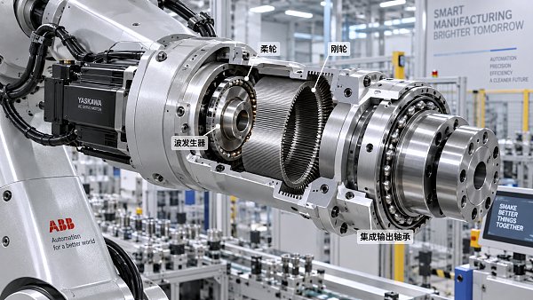
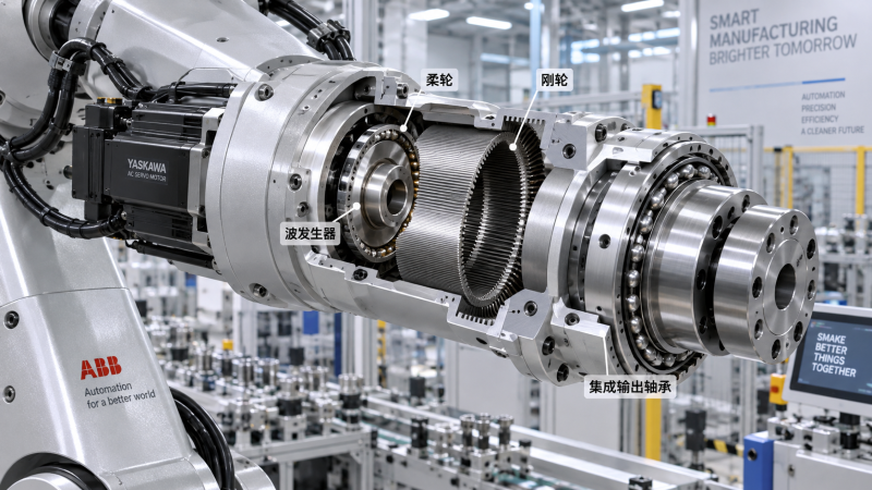
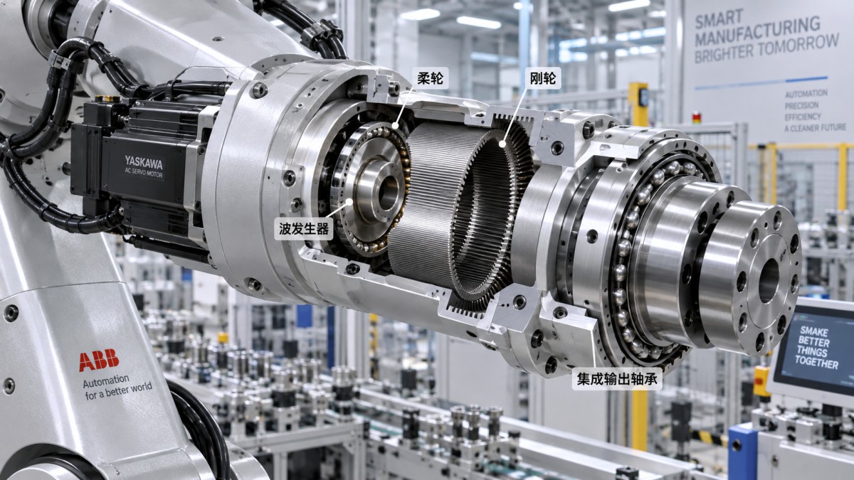
A harmonic drive uses three principal elements: a circular spline with internal teeth, a flexible spline with external teeth, and a wave generator that elastically deforms the flexible spline into an oval shape. The flexible spline engages the circular spline at opposed regions rather than at only one localized tooth contact. Their tooth counts differ slightly, so each input revolution produces a small relative displacement at the output. The arrangement yields a high reduction ratio in one stage and permits tightly controlled engagement with very little lost motion.
Near-zero backlash should not be interpreted as zero positioning error. It means that clearance-driven reversal error is greatly reduced. Under load, the flexspline, bearing system, output flange, and joint housing still deflect. A joint can therefore show excellent repeatability in a lightly loaded test and a measurable position offset under a cantilevered payload. The distinction is important: backlash is a dead zone around torque reversal, while elastic deflection is a load-dependent displacement that changes with torque.
High reduction also increases the motor-side reflected resolution. If a motor encoder detects a small angular increment, the output increment is that value divided by the reduction ratio. This supports fine command granularity without requiring an impractically high-resolution encoder at the output. Yet a high ratio also reflects load inertia toward the motor and limits joint speed for a given motor speed. The selected ratio must therefore support both the minimum controllable motion and the required peak velocity.
Lost motion, torsional stiffness, and repeatability are separate measures
Reducer specifications are often compared as if one number can describe precision. That approach obscures the behavior that matters at the joint. Lost motion, torsional stiffness, transmission error, repeatability, and accuracy describe different phenomena and should be read together.
For point-to-point handling, lost motion and repeatability often dominate the perceived joint behavior. For continuous-path dispensing, scanning, welding, or force-guided finishing, transmission error and stiffness can be equally important. A periodic error that is modest during static indexing can appear as a speed ripple or contour deviation during slow, uniform motion. Closed-loop control may reduce the observed effect, especially with an output encoder, but controller bandwidth cannot fully compensate for mechanical behavior that occurs outside the measurement location.
Stiffness data also requires careful reading. Some catalog values are measured around a specific torque range and may represent an average slope rather than the full torque-angle curve. Harmonic drive assemblies can show non-linear behavior because the flexspline deformation, tooth contact, and bearing preload evolve with applied torque. A single stiffness figure is useful for screening, but design calculations need the relevant portion of the torque-deflection relationship, including the intended preload and direction of loading.
The joint bearing can dominate the result
Many robotic-joint harmonic drives are supplied as integrated units with an output bearing. This is not merely a packaging convenience. The output bearing carries radial load, axial force, and overturning moment while preserving the reducer's alignment. If the application imposes a long offset between the joint center and the payload center of mass, moment load may govern the design even when transmitted torque is comfortably within the reducer rating.
A reducer selected only by nominal torque can perform poorly when the output bearing approaches its permissible moment or when a thin adapter plate bends under load. The visible symptom may resemble gear compliance: the end effector shifts as the arm changes orientation. The source could instead be flange bending, a bearing interface that is not seated flat, or a housing with insufficient local stiffness. Separating these effects requires measurement at several locations. Comparing motor angle, reducer output angle, and a target attached near the load can reveal whether the motion is inside the reducer or in the surrounding structure.
Mounting surfaces deserve the same discipline as the reduction mechanism. Concentricity errors, burrs, paint on locating faces, uneven bolt preload, or distorted pilot diameters can introduce runout and bearing stress. A stiff harmonic drive mounted to a compliant bracket will transmit the bracket's deformation directly to the tool center point. Joint accuracy models should include the installation geometry rather than treating the reducer as an isolated precision component.
Ratio selection changes control behavior
Higher reduction ratios increase output torque and improve output resolution, but they also change the servo system. The motor must accelerate the reflected inertia, overcome reducer friction, and maintain sufficient speed margin at peak joint velocity. A ratio chosen solely for maximum torque can force the motor into high-speed operation during ordinary motion, reducing available voltage margin and making velocity control less robust.
At the opposite extreme, too little reduction leaves more disturbance torque for the motor to reject and reduces the benefit of motor encoder resolution at the output. This can become apparent during gravity-loaded motion, contact transitions, or low-speed tracking. The better comparison is not simply “highest ratio available”; it is whether the ratio keeps the motor in a favorable speed and torque range across the motion profile while providing adequate reflected resolution and disturbance rejection.
Joint dynamics matter as much as steady-state ratings. Rapid pick-and-place motion produces acceleration torque, while a slow vertical hold can produce sustained gravity torque. A process involving repeated reversals subjects the reducer to alternating loads that may be more demanding than a single unidirectional move. The duty cycle should distinguish continuous torque, intermittent peak torque, emergency stop conditions, and externally applied shock. These are separate conditions because the thermal and mechanical consequences are different.
Accuracy under temperature and changing load
Harmonic drives rely on controlled elastic deformation and lubricated rolling or sliding contacts. Temperature changes alter lubricant viscosity, preload behavior, friction torque, and the dimensions of surrounding parts. A joint tuned when cold can show a different breakaway torque and settling response after extended motion. At low speed, the effect may present as stick-slip or a small following error that is not present at higher velocity.
Thermal expansion can also affect assembly interfaces. If the reducer housing, output flange, and joint casing use different materials or experience unequal heating, fit conditions may shift. The resulting error is rarely described by a simple linear correction because heat distribution changes with posture, ambient conditions, motor loading, and nearby equipment. Where thermal stability is important, test cycles should include warm-up, sustained operation, and cooldown rather than recording only an initial static measurement.
Load direction changes deserve similar attention. A payload that always applies torque in one direction can mask lost-motion behavior because the tooth contacts remain biased. When the same joint performs bidirectional scanning or alternates between supported and unsupported orientations, contact forces cross through reversal. That is the condition in which backlash, friction hysteresis, encoder quantization, and controller deadband become visible. Tests that approach every target from only one direction can therefore overstate usable positional performance.
Encoder placement determines what the controller can correct
A motor-side encoder measures motor rotation before reducer compliance and output-bearing deflection. With a rigid load and predictable transmission, this arrangement can provide strong control performance. It cannot directly observe an output shift caused by reducer windup, bearing deflection, or structural bending. The controller may hold the motor precisely while the end effector moves under an external force.
An output encoder measures closer to the controlled quantity and can reduce sensitivity to transmission error and compliant deflection within the feedback loop. Its installation introduces its own concerns: encoder runout, shaft attachment, signal integrity, resolution, reference repeatability, and the dynamic phase lag created by a flexible mechanical path. The feedback architecture should match the task. A high-bandwidth motor loop with a slower outer position loop is often used where output position must be controlled without exciting mechanical resonances.
Dual-encoder architectures are especially informative during development because the difference between motor-side and output-side position exposes elastic twist and lost-motion behavior. The measurement is not a universal remedy. If the arm itself bends between the encoder location and the tool center point, additional kinematic compensation or external metrology may still be required.
Benchmarking a harmonic drive assembly
A useful comparison starts by defining the joint rather than extracting a single catalog number. The relevant load case includes output torque, radial and axial loads, overturning moment, speed, acceleration, reversal frequency, mounting orientation, duty cycle, lubricant temperature range, and required service life. Values should be tied to the actual axis geometry. A nominal torque transmitted through a centered flange is not equivalent to the same torque combined with a large cantilevered moment.
- Record the torque-angle curve in both directions over the operating torque window. This distinguishes a narrow reversal dead band from broader elastic hysteresis.
- Measure angular error across a complete output revolution at the intended speed, then repeat under representative payload. Periodic deviations that are harmless for indexing can be objectionable in contour motion.
- Apply radial load, axial force, and moment separately before evaluating realistic combined loading. An integrated output bearing may have different limits for each condition, and combined loads reduce the available margin.
- Run the assembly through a thermal cycle before final servo tuning. Friction, settling time, and position offset should be compared at stabilized temperatures rather than inferred from a short unloaded run.
- Inspect the full mounting stack: pilot fits, flange flatness, bolt pattern, torque sequence, cable strain relief, and the stiffness of the adjacent arm sections.
Specification terminology must also be aligned before comparing products. “Backlash,” “lost motion,” “angular transmission error,” and “positioning accuracy” are not always measured with the same test torque, output orientation, temperature, or fixture stiffness. A small published value measured under a lightly loaded, one-direction approach does not directly predict bidirectional accuracy in an assembled robot. The test method is part of the result.
Assembly details that preserve precision
Installation errors often appear after the joint has passed an incoming inspection. The reducer should be supported according to its intended load path during assembly. Forcing a unit into an interference condition with mounting bolts, using bolts to pull misaligned pilots together, or tightening a flange unevenly can distort the output interface. Tightening patterns and specified fastener preload are functional requirements because they affect contact flatness and joint stiffness.
Lubrication should remain consistent with the reducer design. Substituting a lubricant without confirming compatibility can alter friction, wear behavior, and seal performance. Overfilling a confined joint can increase churning losses and heat; insufficient lubricant can accelerate damage at high load. Any local sealant, cleaning solvent, or adhesive used near the reducer must be controlled so contamination does not reach the internal mechanism.
After assembly, a low-speed bidirectional sweep is more revealing than a single homing move. Monitoring motor current, output position, and temperature during this sweep can expose abnormal friction, misalignment, cable interference, or unexpected reversal behavior before the axis is integrated into a full motion sequence. The aim is not to force a precision value from one test, but to verify that the installed joint behaves consistently with the mechanical assumptions used in the design.
A harmonic drive delivers its strongest precision advantage when its high reduction, low lost motion, stiffness, bearing capacity, encoder strategy, and mounting structure are treated as one joint-level design problem. That view prevents a common mismatch: selecting an excellent reducer and then losing its accuracy through load geometry, compliance, or measurement choices outside the reducer itself.
Recommended News
 Oct 12, 2026How harmonic drives improve precision in robotic jointsRobotic joints harmonic drive solutions improve precision with low lost motion, high stiffness, and compact torque control. Explore key design insights for accurate robot motion.
 Oct 11, 2026What should a manufacturing intelligence platform dashboard show first?Manufacturing intelligence platform dashboard essentials: prioritize actionable exceptions, production constraints, quality, asset health, supply risk, and energy insights.
 Oct 10, 2026Can predictive manufacturing analytics reduce unplanned downtime?Manufacturing analytics predictive strategies can reduce unplanned downtime by detecting equipment risks early, improving maintenance decisions, and protecting critical production assets.
 Oct 08, 2026How to build quality assurance compliance into supply chain workflowsQuality assurance compliance made practical: build risk-based workflow gates, traceability, supplier controls, and release discipline to prevent costly supply chain failures.
 Oct 07, 2026Where manufacturing intelligence delivers the fastest gains in North AmericaManufacturing intelligence North America: discover where plants gain fastest through reliability, quality, supply visibility, and energy optimization.
 Oct 06, 2026How to vet a packaging materials supplier for consistent qualityPackaging materials supplier vetting made practical: assess quality controls, traceability, trials, change management, and supply resilience for reliable performance.
 Oct 05, 2026How to prepare for a quality assurance audit without disrupting productionQuality assurance audit preparation made practical: protect production, organize evidence, close risks, and build lasting compliance confidence.
 Oct 04, 2026When does bamboo cosmetic packaging make sense for skincare brands?Bamboo cosmetic packaging: learn when it delivers premium skincare appeal, how to manage performance risks, and what brands need for credible sustainability claims.
 Oct 03, 2026What drives hydraulic filtration system price in industrial equipment?Hydraulic filtration system price depends on flow, micron rating, pressure, materials, and lifecycle costs. Learn how to compare options and choose smarter.
 Oct 02, 2026What makes an industrial resilience dashboard useful during disruptions?Industrial resilience dashboard: discover how real-time risk, impact, response, and recovery insights help leaders protect continuity and act decisively during disruptions.
 Oct 01, 2026What to verify before selecting an industrial data platforms supplierIndustrial data platforms supplier selection guide: verify connectivity, security, data governance, scalability, AI readiness, and support before choosing a platform.
 Sep 30, 2026Semiconductor equipment guide for evaluating tool uptime requirementsSemiconductor equipment guide for evaluating tool uptime requirements, downtime risks, service support, predictive maintenance, and lifecycle performance.
 Sep 29, 2026How hydraulic digital twin simulation helps predict cavitation riskHydraulic digital twin simulation helps predict cavitation risk with physics-based pressure insights, enabling smarter maintenance, safer operations, and reliable asset decisions.
 Sep 28, 2026Can a semiconductor automation manufacturer meet your cleanroom specs?Semiconductor automation manufacturer selection starts with cleanroom proof. Learn how to assess contamination control, materials, airflow, validation evidence, and serviceability before you buy.
 Sep 27, 2026What drives high pressure hydraulic hose price differences?High pressure hydraulic hose price differences explained: compare materials, pressure ratings, assembly quality, traceability, and lifecycle value for smarter sourcing.
 Sep 26, 2026How to calculate hydraulic oil cooler sizing for peak heat loadHydraulic oil cooler sizing for peak heat load: calculate losses, duty cycles, temperature differences, flow, and pressure drop to select the right cooler.
 Sep 25, 2026How smart inspection technology for electronics reduces false defect callsSmart inspection technology for electronics reduces false defect calls with AI-assisted imaging, adaptive rules, and traceable quality decisions. Learn how to improve yield and trust.
 Sep 24, 2026How to qualify a protective coatings manufacturer for corrosion controlProtective coatings manufacturer qualification guide: assess corrosion performance, quality control, application support, compliance, and supply reliability for safer, longer-lasting assets.
 Sep 23, 2026Where machine vision delivers the most value in intelligent automationIntelligent automation applications with machine vision drive measurable value in quality, material handling, uptime, and traceability. Explore scalable strategies for resilient operations.
 Oct 02, 2026Supplier data issues that quietly distort sourcing decisionsSupplier data issues can quietly undermine sourcing decisions. Discover how to validate capability, capacity, compliance, and evidence for more resilient procurement.
 Oct 01, 2026How supplier data issues create duplicate spend recordsSupplier data issues can create duplicate spend records, distort approvals, and hide supplier exposure. Discover practical controls to improve visibility and reduce risk.
 Sep 30, 2026What automation downtime patterns reveal before a line stopsAutomation downtime patterns can reveal risks before a line stops. Learn how alarms, micro-stops, cycle-time drift, and sensor faults support proactive maintenance.
 Sep 29, 2026How supply market intelligence for procurement professionals reduces bid riskSupply market intelligence for procurement professionals helps reduce bid risk, validate supplier claims, uncover hidden dependencies, and build resilient sourcing strategies.
 Sep 28, 2026Where factory floor AI delivers useful alerts rather than noiseFactory floor AI turns complex production data into timely, actionable alerts—reducing noise, preventing quality drift, and protecting throughput.