Search News
Industry Portal
Popular Tags
Diagnosing Thickness Variation on an Artificial Leather Calendering Line
Author
Time
Click Count
Thickness variation is usually a process signal, not a single-setting error
When an artificial leather sheet leaves the calender with an uneven gauge, operators may see heavier edges, a thin centre band, repeating stripes, random cross-direction swings, or gradual changes from one roll to the next. The visible defect can look similar in each case, but the underlying causes are often very different. A roll temperature imbalance, unstable bank, worn roll surface, inconsistent compound viscosity, or a drifting thickness-control system can all produce material that fails the same basic gauge check.
This matters because calendered synthetic leather is rarely judged by thickness alone. Gauge variation can change embossing definition, feel, tensile behaviour, coating consumption, lamination performance, and the way the product behaves during downstream cutting or sewing. If the base sheet is thin in one area and heavy in another, the following process may compensate unevenly rather than correct the defect. That can conceal the root cause while increasing scrap, rework, and material usage.
A useful diagnosis starts by treating thickness as a pattern. Operators should record where the variation appears, whether it repeats at a fixed interval, whether it changes with speed or temperature, and whether it is present before or after a particular operation. Those observations narrow the search much faster than adjusting nip pressure repeatedly and hoping for improvement.
Read the thickness profile before changing the machine
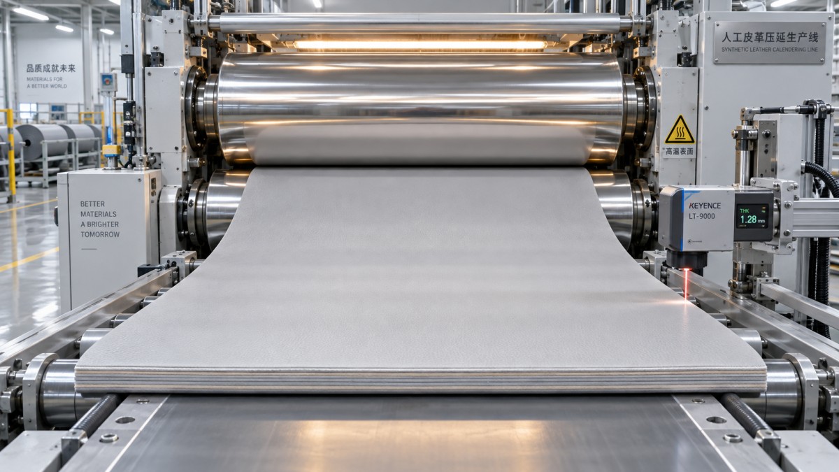
The first question is whether the variation runs in the machine direction, across the web, or both. A simple cross-web profile taken at a consistent sampling interval can distinguish a stable profile problem from random process noise. Measurements should be taken after the sheet has cooled sufficiently to avoid confusing thermal shrinkage or tension effects with actual calender output.
The pattern should be linked to the exact product structure. A compact PVC formulation, a foamed layer, a plastisol-coated substrate, and a thermoplastic polyurethane construction do not respond in the same way. Material that appears adequately fused at one speed may become less uniform at another because viscosity, air release, and heat penetration change with residence time. For that reason, a diagnosis should always identify the formulation, batch, backing construction, target thickness, line speed, and actual temperature readings rather than relying only on nominal recipes.
Start upstream: material consistency and feed conditions
Thickness control at the calender cannot fully correct a compound that arrives at the nip inconsistently. Variations in plasticizer distribution, filler dispersion, pigment concentration, moisture pickup, recycled-content blend, or holding time can alter flow behaviour. Even when the total mass fed to the line seems correct, a material with changing viscosity may spread differently across the roll face. The result can be an unstable bank and a changing gauge profile.
Operators should inspect the feed in practical terms. Does the bank remain even across the working width? Does material build at one side? Is the bank level changing in a regular cycle? Does the sheet width fluctuate before it reaches the finishing nip? A bank that is too small may expose the process to short-term feed fluctuations. A bank that is too large can increase residence time and may create uneven temperature history across the width.
Feed equipment deserves the same attention as the calender stack. A worn screw, inconsistent screw speed, bridging in the hopper, poor temperature control in a preheater, or unstable extrusion pressure can create a thickness problem that appears to originate at the rolls. If the line uses multiple feeding points, check whether each stream has comparable temperature and output. A small mismatch can become obvious after the material is spread across a wide nip.
Separate batch effects from machine effects
A fast way to separate material behaviour from equipment behaviour is to compare retained samples or a known stable formulation under similar operating conditions. If the profile improves when the material changes but the roll settings remain fixed, the investigation should return to mixing, ageing, storage, or feed preparation. If the same defect remains across batches and shifts with a roll adjustment, mechanical or thermal causes become more likely.
That comparison should be controlled. Changing the compound, roll temperature, speed, and nip force at the same time makes the result difficult to interpret. One deliberate adjustment, followed by enough run length to stabilize the process, produces more useful evidence than many rapid corrections.
Check the nip as a thermal and mechanical system
A calender nip does not produce a uniform sheet simply because the roll gap has been set to a target value. Under load, rolls deflect. Under heat, they expand. Their surface condition affects friction and release. The material itself can generate a changing hydraulic pressure within the bank. Gauge uniformity comes from the interaction of these factors, not from one dial or one hydraulic reading.
Cross-direction variation often points to a mismatch between the expected and actual nip shape. In some situations, centre thickness suggests insufficient compensation for roll deflection. In others, the centre is thin because the material bank is concentrated there or because loading and roll geometry are producing excessive centre pressure. The right correction depends on measured profile data. Raising overall pressure may reduce average thickness while worsening the cross-web difference.
Check whether the loading system responds equally on both sides, whether pressure indications agree with actual mechanical movement, and whether adjustment mechanisms have backlash or delayed response. For older equipment, worn journals, bearing clearance, damaged loading cylinders, or frame alignment can make a stable gap impossible to maintain under production load. A cold inspection alone may not reveal the issue; some faults become visible only after the rolls reach operating temperature and the line is under tension.
Roll temperature should be measured at more than one location where practical. A controller can show a stable setpoint while the roll surface has meaningful edge-to-centre differences because of restricted heat-transfer flow, scaling, blocked passages, poorly balanced circulating fluid, or sensor placement. Uneven temperature changes material viscosity across the web. It can also affect roll expansion and alter the actual nip profile.
Look for periodic defects that point to rotating components
Repeated thick and thin bands are especially valuable clues. If a defect returns at a distance close to a roll circumference, inspect that roll for eccentricity, runout, damaged bearings, localized surface damage, or build-up that has not been removed consistently. A smaller repeating interval may be associated with an idler, pull roll, embossing roll, or another rotating component downstream of the main calender.
Surface contamination can create a misleading profile. Deposits on a roll may locally change friction, heat transfer, or effective diameter. Depending on the material and release behaviour, the sheet may drag, slip, or be compressed differently at the affected point. Cleaning should be followed by a profile check, not merely a visual inspection, because a polished-looking surface can still have localized wear or damage.
Vibration is another possible contributor. Loose foundations, coupling wear, gearbox issues, poor bearing condition, or an unstable drive can produce short-cycle nip variation. Operators may hear or feel a machine change before gauge data makes the pattern obvious. These observations should be logged with roll speed and defect frequency; they can help maintenance personnel relate the variation to a particular component.
Do not overlook web tension and downstream handling
Not every apparent thickness defect is created in the main calender. A hot sheet can stretch under excessive tension, particularly where its temperature remains high or where the backing and polymer layer respond differently. Uneven tension across the width can distort the material, while fluctuating tension can create machine-direction gauge changes. Cooling conditions also matter: uneven chill-roll contact, poor wrap control, or a web that is wound too warm can influence the final measured thickness.
To isolate this possibility, measure at more than one point in the process when safe sampling is possible. A sheet that is uniform immediately after the final nip but variable after cooling or winding directs attention to draw, cooling, and handling equipment. If the defect is already present at the nip exit, the investigation should focus upstream.
Backing material can complicate the result. Fabric tension, moisture condition, weave variation, and thickness inconsistency may affect how the polymer layer is carried through the process. When a backing is involved, inspect the incoming roll for width variation, wrinkles, telescoping, and tension differences between the two edges. A calender setting that works on one backing construction may not transfer directly to another.
Use a disciplined correction sequence
When production pressure is high, operators may be tempted to keep changing roll gap, temperature, speed, and feed rate until the gauge appears acceptable. That approach can create a process that works only briefly and makes recurring faults harder to identify. A better sequence is to confirm the measurement, characterize the pattern, stabilize the material feed, verify mechanical and thermal conditions, then make one controlled correction at a time.
- Confirm the gauge data. Check sampling location, instrument condition, cooling state, and whether readings represent the full width and roll length.
- Capture operating conditions. Record actual speed, roll temperatures, loading conditions, feed output, bank appearance, web tension, and batch identification.
- Determine the defect signature. Identify whether variation is cross-directional, machine-directional, cyclic, edge-related, or linked to a production change.
- Inspect the simplest reversible causes. Review feed consistency, temperature balance, cleaning condition, tension settings, and visible roll or guide issues before major mechanical intervention.
- Test one variable with a defined expectation. For example, if edge temperature is suspected, correct the thermal imbalance and verify whether the edge profile changes in the predicted direction.
- Escalate persistent patterns. Stable periodic defects, poor loading response, or profile drift under heat may require runout checks, alignment work, hydraulic inspection, or roll-service evaluation.
Used-line checks should focus on evidence, not appearance
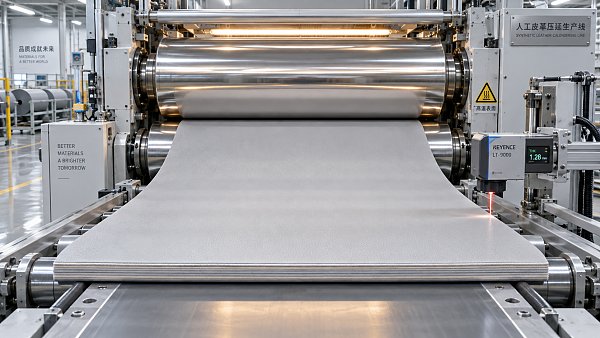
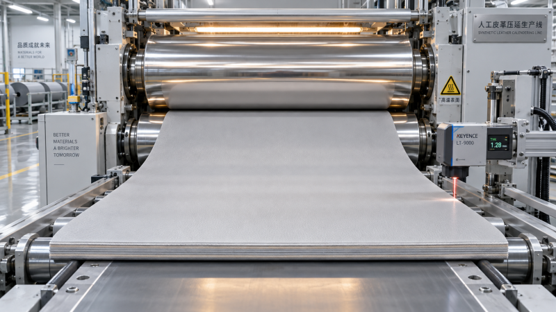
For operators commissioning refurbished or previously operated equipment, thickness capability should be assessed as a system. A line may have sound-looking rolls while its temperature circuits, loading controls, drives, gauges, or handling sections limit stable production. Reference information on a artificial leather calendering line can help frame the equipment category, but the practical evaluation should still concentrate on the condition of the actual machine and its supporting systems.
Before acceptance or restart, examine maintenance records where available, roll surface condition, bearing history, hydraulic leakage, instrumentation function, heating and cooling circuit cleanliness, and the condition of gearboxes and couplings. Confirm that safety guards and emergency functions are operational before any running test. During a test run, observe whether the rolls heat evenly, whether the nip responds predictably to adjustment, and whether the web remains stable across the intended operating range.
A trial using only a short strip or narrow web may fail to expose full-width deflection and temperature problems. The most meaningful validation uses a representative width, material family, and line speed, with thickness measurements across the sheet rather than a single centre reading. Where a full production trial is not possible, the remaining uncertainty should be recognized in commissioning plans and spare-parts preparation.
Keep the process stable after the defect disappears
Once thickness variation is corrected, the settings and conditions that produced the stable profile should become part of the operating record. Include actual temperatures rather than only controller setpoints, normal bank appearance, acceptable pressure response, speed range, tension settings, and the gauge sampling method. This provides a baseline when a later batch or maintenance event changes line behaviour.
Thickness variation is easiest to manage when it is treated as evidence from the whole process: material preparation, feed, nip geometry, thermal control, rotating equipment, and web handling. The operator who identifies the defect pattern before adjusting the machine is more likely to correct the cause instead of merely shifting the problem to the next stage.
Recommended News
 Sep 30, 2026Semiconductor equipment guide for evaluating tool uptime requirementsSemiconductor equipment guide for evaluating tool uptime requirements, downtime risks, service support, predictive maintenance, and lifecycle performance.
 Sep 29, 2026How hydraulic digital twin simulation helps predict cavitation riskHydraulic digital twin simulation helps predict cavitation risk with physics-based pressure insights, enabling smarter maintenance, safer operations, and reliable asset decisions.
 Sep 28, 2026Can a semiconductor automation manufacturer meet your cleanroom specs?Semiconductor automation manufacturer selection starts with cleanroom proof. Learn how to assess contamination control, materials, airflow, validation evidence, and serviceability before you buy.
 Sep 27, 2026What drives high pressure hydraulic hose price differences?High pressure hydraulic hose price differences explained: compare materials, pressure ratings, assembly quality, traceability, and lifecycle value for smarter sourcing.
 Sep 26, 2026How to calculate hydraulic oil cooler sizing for peak heat loadHydraulic oil cooler sizing for peak heat load: calculate losses, duty cycles, temperature differences, flow, and pressure drop to select the right cooler.
 Sep 25, 2026How smart inspection technology for electronics reduces false defect callsSmart inspection technology for electronics reduces false defect calls with AI-assisted imaging, adaptive rules, and traceable quality decisions. Learn how to improve yield and trust.
 Sep 24, 2026How to qualify a protective coatings manufacturer for corrosion controlProtective coatings manufacturer qualification guide: assess corrosion performance, quality control, application support, compliance, and supply reliability for safer, longer-lasting assets.
 Sep 23, 2026Where machine vision delivers the most value in intelligent automationIntelligent automation applications with machine vision drive measurable value in quality, material handling, uptime, and traceability. Explore scalable strategies for resilient operations.
 Sep 29, 2026How supply market intelligence for procurement professionals reduces bid riskSupply market intelligence for procurement professionals helps reduce bid risk, validate supplier claims, uncover hidden dependencies, and build resilient sourcing strategies.
 Sep 28, 2026Where factory floor AI delivers useful alerts rather than noiseFactory floor AI turns complex production data into timely, actionable alerts—reducing noise, preventing quality drift, and protecting throughput.
 Sep 27, 2026What vertical AI manufacturing platforms can automate in changeoversVertical AI manufacturing platforms streamline changeovers with smarter planning, configuration matching, guided execution, and first-piece readiness—reducing downtime and risk.
 Sep 26, 2026Choosing a low noise pump for a power unit when space is limitedLow noise pump for power unit selection made simple: compare noise paths, compact layouts, thermal limits, and service access for reliable performance.
 Sep 25, 2026What a low dBA hydraulic pump rating does and does not tell youLow dBA hydraulic pump ratings explained: compare test conditions, vibration paths, pressure ripple, and installation factors to make smarter, quieter system choices.
 Sep 24, 2026Hydraulic pump noise reduction starts with finding the dominant sourceHydraulic pump noise reduction starts with identifying the dominant source. Learn to diagnose cavitation, aeration, pulsation, and drive faults for reliable repairs.
 Sep 23, 2026When silent hydraulic pump wholesale pricing signals a quality riskSilent hydraulic pump wholesale pricing can reveal hidden quality risks. Learn how to compare specifications, testing, traceability, and support before sourcing.
 Sep 30, 2026Diagnosing Thickness Variation on an Artificial Leather Calendering LineDiagnose thickness variation on an artificial leather calendering line with practical checks for feed, nip pressure, roll temperature, tension, and recurring defects.
 Sep 22, 2026How to assess a servo motors manufacturer’s quality control processServo motors manufacturer quality control guide: assess traceability, process capability, testing, calibration, and change control to reduce automation risk.
 Sep 21, 2026How bearing friction torque data affects servo actuator sizingBearing friction torque data is essential for accurate servo actuator sizing. Learn how preload, speed, temperature, and friction affect torque, thermal margin, and control stability.
 Sep 20, 2026How to use an electronics product reference to verify component compatibilityUse an electronics product reference to verify component compatibility with confidence. Compare electrical, pin, thermal, mechanical, firmware, and lifecycle requirements before approving replacements.
 Sep 19, 2026When can a supply chain LLM reduce time spent finding shipment updates?Supply chain LLMs can cut shipment-update search time by connecting carrier events, ERP data, and documents—giving teams traceable answers and faster exception response.
 Sep 18, 2026How industrial monitoring equipment helps prevent unplanned downtimeIndustrial monitoring equipment helps teams detect early asset issues, prioritize maintenance, and prevent costly unplanned downtime. Explore practical strategies for reliable operations.
 Sep 17, 2026What next-gen harmonic drive research means for robot joint accuracyNext-gen harmonic drive research reveals how backlash, stiffness, thermal drift, and sensing shape robot joint accuracy. Explore smarter validation strategies.
 Sep 16, 2026How Southeast Asian climates affect cylinder seal frictionCylinder seal friction Southeast Asia: learn how humidity, heat, monsoons, and contamination affect motion stability, wear, and seal selection.
 Sep 15, 2026How to size DC gear motors for the required starting torqueGear motors DC sizing made practical: calculate starting torque, account for friction, gravity, inertia and voltage drop, then select a reliable motor with confidence.