Search News
Industry Portal
Popular Tags
How to calculate hydraulic cylinder load rating from pressure
Author
Time
Click Count
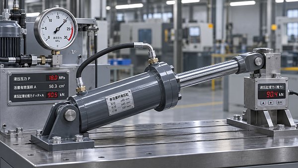
A hydraulic cylinder’s force can be calculated from pressure and effective piston area, but pressure alone does not establish the cylinder’s load rating. Bore diameter determines the area available for extension; rod diameter reduces the area available for retraction. Pressure on the opposite side of the piston, friction, mounting geometry, and the length of the extended rod can further change what the assembly can safely move or hold.
For an initial calculation, multiply the pressure difference acting across the relevant effective area by that area. In a conventional cylinder with negligible pressure on the return side, this simplifies to pressure multiplied by piston area for extension, or pressure multiplied by annular area for retraction. Treat the result as theoretical hydraulic force, not automatically as an approved working load.
Calculate force from pressure and effective area
The basic relationship is:
Force = pressure × effective area
In metric units, pressure in bar and area in square centimeters give force in kilonewtons:
Force (kN) = pressure (bar) × effective area (cm²) ÷ 100
In US customary units, pressure in pounds per square inch and area in square inches give force in pounds-force:
Force (lbf) = pressure (psi) × effective area (in²)
Use the internal bore diameter to calculate piston area. Do not use the cylinder’s outside diameter: wall thickness does not contribute to the pressure-loaded piston area.
Piston area = π × bore diameter² ÷ 4
For a single-rod cylinder, extension pressure acts on the full piston area. During retraction, the rod occupies part of the piston face, so pressure acts on the smaller annular area:
Annular area = π × (bore diameter² − rod diameter²) ÷ 4
These equations assume consistent diameter and area units. They also assume that the opposite chamber has negligible gauge pressure. If it does not, calculate the forces on both sides and subtract the opposing force.
A worked example: extension and retraction
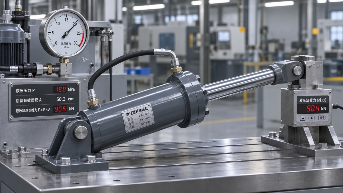
Consider a single-rod cylinder with a 100 mm bore and a 50 mm rod. Assume that the pressure at the active cylinder port is 160 bar and that pressure at the opposite port is negligible. The dimensions are illustrative; they do not describe a particular cylinder or establish its allowable load.
Convert the diameters to centimeters: the bore is 10 cm and the rod is 5 cm. Using π ≈ 3.1416:
The same 160 bar therefore produces approximately 125.7 kN in extension and 94.3 kN in retraction under the stated assumptions. The difference comes from the rod’s displacement of part of the pressure-loaded area. A design that requires the same force in both directions must account for the smaller retracting area.
To express force as a mass-equivalent under standard gravity, divide kilonewtons by approximately 9.81 to obtain metric tonnes. In the example, 125.7 kN corresponds to roughly 12.8 tonnes-force. That conversion is useful for interpreting a vertical static load, but it does not mean the cylinder is rated to lift or hold a 12.8-tonne mass. The actual mechanism and operating limits still govern.
Account for pressure on both sides
A system pressure setting is not necessarily the pressure available at the cylinder port. Flow through valves, hoses, fittings, and other components creates pressure losses. The return side may also have backpressure, particularly when oil must pass through a restrictive circuit or a load-control valve.
For a single-rod cylinder, calculate the net hydraulic force as follows, using pressures and areas in consistent units:
- Extension: cap-end pressure × full piston area − rod-end pressure × annular area.
- Retraction: rod-end pressure × annular area − cap-end pressure × full piston area.
The result is the ideal net force before internal friction and other mechanical losses. Use gauge pressures referenced to the same datum and consider the pressures that can occur together in the operating condition being evaluated.
For example, if the cylinder above has 160 bar at the cap end and 20 bar at the rod end during extension, the ideal net force is:
(160 × 78.54 − 20 × 58.91) ÷ 100 = 113.9 kN
That is about 11.8 kN less than the calculation that assumes zero rod-end pressure. The loss is not a fixed percentage of the original answer: it depends on return-side pressure and annular area. For a moving load, pressure measurements or a circuit calculation at the relevant flow rate give a better basis than the pump’s relief-valve setting alone.
Check the hydraulic circuit before applying the simple formulas. A double-rod cylinder has a different effective area arrangement, while a regenerative circuit can pressurize both sides during extension. In either case, the force follows from the pressure and effective area on each side, but the one-sided extension formula may give the wrong answer.
Work backward from the required load
When sizing a cylinder, start with the force required at the cylinder rod, not necessarily the weight of the object being moved. A linkage can provide mechanical advantage in one position and require much more cylinder force in another. Calculate the demanding position and direction across the intended stroke, including acceleration, friction in the machine, and external process forces where relevant.
For a first-pass extension estimate with negligible opposing pressure:
Required piston area (cm²) = required force (kN) × 100 ÷ available pressure (bar)
Required bore diameter = √(4 × required piston area ÷ π)
Suppose the cylinder must deliver 100 kN of theoretical extension force at 160 bar. The required piston area is 62.5 cm², corresponding to a bore of approximately 8.9 cm, or 89 mm. This is a mathematical minimum under the assumptions, not a final bore selection. It leaves no allowance for backpressure, cylinder friction, variations in load, or a design margin.
If return-side pressure is significant, the equation must include the opposing annular-area force. Since that area depends on the rod diameter, bore and rod selection may need to be evaluated together. Retraction sizing also requires the rod diameter because the required force must come from the annular area rather than the full bore area.
Why calculated force is not a load rating
A cylinder can develop a theoretical hydraulic force that exceeds what its rod, mountings, or supporting structure can safely carry in a given installation. Evaluating a hydraulic cylinder load rating therefore requires at least two separate checks: whether the hydraulic circuit can produce the required force, and whether the cylinder assembly can withstand and transmit it.
Rod buckling and mounting
In compression, an extended piston rod can buckle before hydraulic pressure reaches the cylinder’s pressure limit. The risk depends on unsupported length, rod diameter, end restraints, alignment, material properties, and the way the load is applied. A long-stroke cylinder pushing a load is therefore not interchangeable with a short-stroke cylinder of the same bore, rod diameter, and pressure rating.
Mounting style matters because it changes how the rod and cylinder are restrained. Misalignment or side loading can also increase bearing and rod loading. Use the manufacturer’s buckling guidance or an appropriate engineering calculation for the installed geometry and maximum extended position. The bore-and-pressure equation alone cannot supply this limit.
Pressure limits and transient conditions
The cylinder’s allowable working pressure must be compatible with the circuit, including pressures that can occur during operation. A relief-valve setting does not describe every transient at every point in a circuit. Deceleration, external loads, trapped oil, and pressure intensification can create local conditions that require separate review.
Pressure intensification deserves particular attention when an external load drives the cylinder or oil is trapped in one chamber. Because the full piston area and annular area differ, pressure on one side can produce a higher pressure on the other under certain conditions. Check the circuit and component limits for the relevant load direction rather than assuming both ports remain below the supply pressure.
Friction, motion, and holding
Seal and bearing friction reduce the force available to move a load and can make the pressure required to start movement differ from that required to keep moving. The magnitude depends on cylinder design and operating conditions. If a manufacturer supplies efficiency or friction data, use it within its stated range; an assumed universal efficiency can obscure a material difference between designs.
Moving and holding a load are also different duties. A pressure-area calculation describes hydraulic force at a given pressure; it does not establish how long a load will remain in position or whether it can be held safely after pressure loss. Leakage, valve configuration, external forces, and the consequences of unintended movement must be considered in the holding design.
Choose a margin that matches the duty
A margin between calculated capability and required load is necessary because loads, pressure losses, friction, and operating conditions are not perfectly known. There is no single multiplier that turns theoretical force into an acceptable rating for every cylinder. The appropriate allowance depends on the quality of the load data, the severity and frequency of the duty, the consequences of failure, and the design rules governing the machine.
Keep the different limits visible instead of applying one factor indiscriminately. A force margin may address uncertainty in the load calculation, while rod buckling, pressure containment, fatigue, mounting strength, and load holding need their own checks. Applying a larger bore can increase available force, but it can also change required flow, speed, mounting loads, and the pressure-intensification behavior of the circuit.
For a technical comparison, ask for the bore and rod diameters, stroke, mounting arrangement, pressure limits, and any manufacturer-specified force or buckling limits under the proposed conditions. Record whether each quoted force is theoretical or includes friction, and whether it assumes zero backpressure. Two force figures are comparable only when their direction, pressure, effective area, and assumptions are comparable.
The final decision should be based on the most restrictive verified limit for the intended duty. If the hydraulic calculation indicates sufficient force but the extended rod or mounting cannot carry the corresponding load, the pressure calculation has answered only part of the selection question.
Recommended News
 Nov 03, 2026How to calculate hydraulic cylinder load rating from pressureCalculate hydraulic cylinder load rating from pressure and piston area. Explore extension and retraction formulas, worked examples, and key safety limits.
 Nov 03, 2026US Navy Seeks Cargo Drones for TRUAS II Tactical Resupply DemonstrationUS Navy seeks cargo drones for the TRUAS II tactical resupply demonstration. Discover the payload, range and application requirements for suppliers.
 Nov 02, 2026Which industrial standards apply to electronic grade chemicals?Industrial standards guidance for electronics: discover how SEMI, ISO and chemical safety rules apply to electronic-grade chemicals.
 Nov 02, 2026FEMA Sets November 16 Deadline for $250 Million Counter-UAS GrantFEMA’s $250 million Counter-UAS grant closes November 16, 2026. Explore eligible uses and potential opportunities for counter-drone suppliers.
 Nov 01, 2026What drives semiconductor automation costs in a wafer fab?Semiconductor automation cost depends on fab layout, integration, installation, and downtime. Discover how to compare proposals and build a stronger investment case.
 Nov 01, 2026Pentagon Commits $1.1 Billion to Drone Dominance ProgramPentagon Drone Dominance program: Explore the reported $1.1 billion commitment, the 2027 drone target and what it could mean for manufacturers and suppliers.
 Oct 31, 2026How much does a custom mechatronic system cost?Understand mechatronic systems cost, from engineering and software to testing and support. Learn how to scope your project and compare quotes with confidence.
 Oct 31, 2026EHang Establishes Thailand Hub to Advance eVTOL Deployment in Southeast AsiaEHang’s Thailand hub advances eVTOL projects in Southeast Asia. Explore what the AAM sandbox could mean for operators, suppliers and market access.
 Oct 30, 2026How to size high-torque robotic joints for a given payloadSizing robotic joints high torque applications demands more than payload ratings. Learn to calculate torque, assess duty cycles, and select the right actuator.
 Oct 30, 2026Taizhou Bay Drone Standards Pilot Passes Review After Developing 29 StandardsTaizhou Bay drone standards pilot passes review after developing 29 standards. Explore potential impacts on testing, certification and procurement.
 Oct 29, 2026How to size the drive motor for a hydraulic pump test benchSize your hydraulic pump test bench drive motor with confidence. Explore power calculations, torque checks, and duty-cycle guidance to avoid overheating, control costs, and ensure reliable testing.
 Oct 29, 2026FCC Advances Final Rules on Drone Dominance and Advanced Air MobilityExplore proposed FCC drone spectrum rules for 5030–5091 MHz and advanced air mobility. Learn what operators and suppliers should watch before making compliance and procurement decisions.
 Oct 28, 2026Are natural rubber pet toys suitable for aggressive chewers?Are natural rubber pet toys right for aggressive chewers? Discover how to choose durable designs, spot unsafe wear, and make smarter buying decisions for safer playtime.
 Oct 28, 2026Percepto Launches Axion Hardware-Agnostic AI Platform for Infrastructure InspectionsPercepto Axion brings hardware-agnostic AI to infrastructure inspections with 160+ models. Explore how third-party drone and sensor data could enable more flexible inspection workflows.
 Oct 27, 2026How to size power electronics for peak loads in industrial servo drivesSize power electronics for industrial equipment with confidence. Learn to verify peak current, voltage headroom, braking energy, and thermal limits to prevent servo drive trips.
 Oct 27, 2026BAE Systems Adapts T-150 Cargo Drone into TRV-150 Counter-Drone PlatformBAE Systems’ TRV-150 adapts the T-150 cargo drone for counter-drone missions using APKWS rockets. Explore its reported 100% test hit rate, potential cost benefits and key limits.
 Oct 26, 2026How to choose automatic pet feeders for a multi-cat householdChoose automatic pet feeders for your multi-cat home with confidence. Compare portion accuracy, microchip access, and reliability to prevent food theft and simplify mealtimes.
 Oct 26, 2026Shenbei Low-Altitude Equipment Cluster Named to National Public Notice ListShenbei’s low-altitude equipment cluster joins China’s national SME cluster public notice list. Explore what the proposed designation could mean for manufacturers and supply-chain partners.
 Oct 25, 2026How to test trace metals in high-purity chemicals for electronicsTesting high purity chemicals for electronics? Learn how ICP-MS, clean sampling, and validated QC deliver reliable trace-metal results for confident batch release.
 Oct 25, 2026Neuron Digital Becomes First Company to Earn BSI Digital Twin KitemarkNeuron Digital becomes the first company to earn BSI Digital Twin Kitemark certification. Discover what this independent assurance means for security, reliability and buyer confidence.
 Oct 24, 2026How to verify API 6DX compliance for hydraulic valve actuatorsVerify hydraulic API compliance for valve actuators with this API 6DX guide. Learn how to review sizing, traceability, and test records to uncover gaps before acceptance.
 Oct 24, 2026Parallel Flight Partners with Drone Forge to Bring Firefly to Asia-PacificParallel Flight partners with Drone Forge to bring the Firefly heavy-lift hybrid drone to Asia-Pacific. Explore its capabilities for logistics and inspection missions.
 Oct 23, 2026How electrification shapes the hydraulic equipment investment outlookExplore the hydraulic equipment investment outlook as electrification reshapes demand. Compare retrofit options, energy savings, and lifecycle costs to make smarter capital decisions.
 Oct 23, 2026IDSA Highlights NTT DATA’s Data Space Approach to a Balearic Islands Digital TwinExplore NTT DATA’s Balearic Islands digital twin, highlighted by IDSA, and see how data spaces connect shared data with predictive modeling to inform regional decisions.